Pump head and NPSHa Tutorial 1 · water transfer from tank to tank
Size the pump that lifts water from a storage tank to an elevated tank: required head, NPSHa and shaft power in CalcPlant, then the same numbers by hand. About 10 minutes.
Open the finished exampleIf you get stuck, open the finished sheet and compare. If you already have a sheet, you are asked before it is replaced.
1. The problem
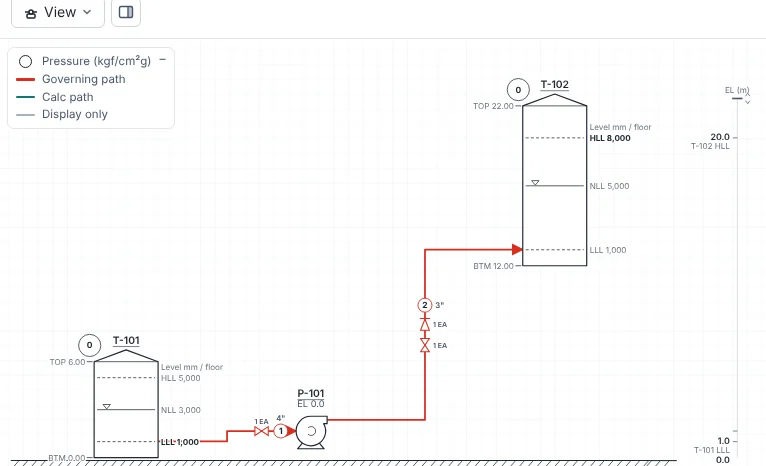
Pump 30 m³/h of water at 20 °C from storage tank T-101 at grade, through pump P-101, to elevated tank T-102 whose bottom is at EL 12 m. Both tanks are open to atmosphere.
| Item | Value | Note |
|---|---|---|
| Fluid | Water 20 °C · ρ 998.2 kg/m³ · μ 1.002 cP | Vapour pressure 0.02385 kgf/cm²a (2.34 kPa) |
| Flow | 30 m³/h | Entered on the suction line |
| T-101 (suction tank) | Bottom EL 0 m · LLL 1,000 mm · HLL 5,000 mm | Operating pressure 0 kgf/cm²g |
| T-102 (destination) | Bottom EL 12 m · HLL 8,000 mm | Operating pressure 0 kgf/cm²g |
| Suction line L1 | 4" Sch 40 (ID 102.3 mm) · 10 m straight | Entrance 1 · gate valve 1 · 90° elbow 2 |
| Discharge line L2 | 3" Sch 40 (ID 77.9 mm) · 60 m straight | Check valve 1 · gate valve 1 · 90° elbow 6 · exit 1 |
| Pump P-101 | EL 0 m · efficiency 70 % · NPSHr 3.0 m | NPSH margin 0.6 m (default) |
Pump head is sized for the worst case: the suction tank at its lowest level (LLL) and the destination at its highest (HLL). The static lift is (12 + 8.0) − (0 + 1.0) = 19.0 m.
2. Place and connect
- Open a blank sheet with File → New.
- In the Equipment list on the left, click Tank twice and Pump once. Rename them T-101, T-102 and P-101.
- Press Connect (shortcut C) and click T-101 → P-101, then P-101 → T-102. Connect in the flow direction; a reversed line makes the pump run backwards.
3. Enter the data
Click an item or a line on the sheet and fill in the Properties panel on the right.
Tanks
- T-101: Bottom Tangent EL 0, levels HLL 5,000 · NLL 3,000 · LLL 1,000 mm, operating pressure 0
- T-102: Bottom Tangent EL 12, level HLL 8,000 mm, operating pressure 0
- Set T-101's Calc level to LLL. A new tank defaults to a more conservative suction basis, the Bottom Tangent (an empty tank); this tutorial works at the LLL. Leave T-102 at its default (discharge HLL).
Pump
- Elevation 0 m, efficiency 70 %, NPSHr 3.0 m. Atmospheric pressure stays at the default 1.033 kgf/cm²a.
- Change the vapour pressure basis to Enter value and enter 0.02385 kgf/cm²a. The default, "Equal to suction vessel (saturated)", is for liquid at its boiling point such as a column or drum; on cold water it gives a far too low NPSHa.
Lines
- L1 (suction): NPS 4 · SCH 40, straight length 10 m, flow 30 m³/h, density 998.2, viscosity 1.002. Valves and fittings: entrance 1, gate 1, 90° elbow 2.
- L2 (discharge): NPS 3 · SCH 40, straight length 60 m, same density and viscosity. Leave the flow empty (it carries on from upstream). Valves and fittings: check 1, gate 1, 90° elbow 6, exit 1.
4. Read the results
| Result | Value | Meaning |
|---|---|---|
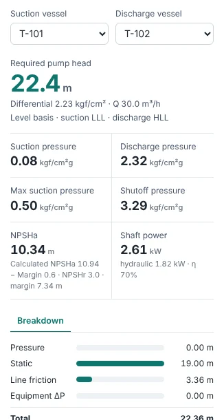
| Required pump head | 22.36 m | Static 19.00 m + line friction 3.36 m |
| Suction / discharge pressure | 0.08 / 2.32 kgf/cm²g | Differential 2.23 kgf/cm², the value for the pump data sheet |
| NPSHa | 10.34 m | Calculated 10.94 m less the 0.6 m margin. It exceeds NPSHr 3.0 m by 7.34 m, ample cavitation margin. |
| Max suction pressure | 0.50 kgf/cm²g | With the suction tank at HLL |
| Shutoff pressure | 3.29 kgf/cm²g | Max suction pressure + differential × 1.25 (motor). Used to check the discharge line design pressure. |
| Shaft power | 2.61 kW | Hydraulic 1.82 kW ÷ efficiency 0.70 |
85 % of the head is static lift and about 15 % is friction. In a system like this a larger pipe does not cut the head much; section 6 shows it.
5. Check by hand
Working the same case by hand gives the CalcPlant numbers. The equations are in Calculation theory §2 and §3.
K = Km/Re + Ki(1 + Kd/Dn0.3) 3-K (Darby), Dn in inches; entrance 160/Re + 0.5, exit 1.0
h = (f·L/D + ΣK) · v²/2g, H = Δz + Σh
| Line | v m/s | Re | f | ΣK | v²/2g m | Pipe m | Fittings m | Total m |
|---|---|---|---|---|---|---|---|---|
| L1 suction 4" | 1.014 | 103,324 | 0.02003 | 1.314 | 0.0524 | 0.103 | 0.069 | 0.172 |
| L2 discharge 3" | 1.748 | 135,688 | 0.01998 | 5.090 | 0.1559 | 2.399 | 0.793 | 3.192 |
ΣK breakdown: L1 = entrance 0.502 + gate 0.135 + elbow 0.339 × 2; L2 = check 1.794 + gate 0.143 + elbow 0.359 × 6 + exit 1.0.
NPSHa = Patm/ρg + zs − hs − Pv/ρg = 10.349 + 1.0 − 0.172 − 0.239 = 10.94 m less 0.6 m margin → 10.34 m
Phyd = ρgQH = 1.82 kW, Pshaft = 1.82 / 0.70 = 2.61 kW
Shutoff = 0.50 + 2.23 × 1.25 = 3.29 kgf/cm²g
test-tutorial-pump) checks this on every run, so if the calculation engine changes the numbers, this page is updated with it.6. Try other pipe sizes
Click discharge line L2 and change only its NPS to 2", 3" and 4". The results recalculate at once.
| L2 size | Velocity m/s | L2 loss m | Required head m | Shaft power kW | Shutoff kgf/cm²g |
|---|---|---|---|---|---|
| 2" Sch 40 | 3.85 | 21.85 | 41.02 | 4.78 | 5.62 |
| 3" Sch 40 | 1.75 | 3.19 | 22.36 | 2.61 | 3.29 |
| 4" Sch 40 | 1.01 | 0.87 | 20.04 | 2.34 | 3.00 |
- 2": loss grows with the square of velocity. Friction now exceeds the static lift and the head almost doubles.
- 4": 2.3 m less head than 3", at a higher pipe and valve cost.
- Pump discharge velocities are often reviewed against a range of roughly 1–3 m/s; here 3" is the balance point. Follow your company design basis for the actual choice.
7. Common mistakes
- Line drawn against the flow: connect in the flow direction and check the arrow on the sheet.
- Flow only on the discharge line: enter it on the line leaving a vessel so it carries downstream.
- Saturated vapour-pressure basis on a cold liquid: water in a tank needs its vapour pressure entered. Left at saturated, this example shows an NPSHa of about 0.2 m, far below the 3.0 m NPSHr.
- Applying the NPSH margin twice: the NPSHa shown already has the 0.6 m margin taken off; the calculated value is in the small text below it.
- Sizing on normal levels (NLL): use suction LLL (or Bottom Tangent) and discharge HLL for head, suction HLL for design pressure. Check which basis each tank's Calc level uses.
The next tutorial covers automatic flow balancing in a cooling-water system split across several exchangers. You can already open the cooling-water examples from the Example menu.